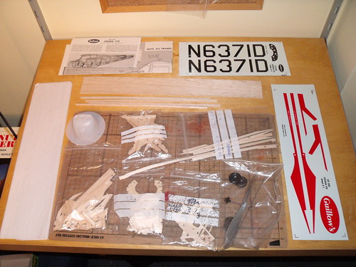
I've recieved new balsa sheets from Guillows for this project.
All five sheets weigh only 6g more than just two of the sheets that came in the kit.
This could not have been an economic excercise for Guillows especially given my location, and it is therefore very comendable of them to replace them.....
Let the building begin.....
300 Series Cessna 170 Build
-
Phugoid
- Posts: 952
- Joined: Wed Jan 20, 2010 8:17 am
I've finally got round to building this one.
I'm going to use the kit contents other than the rubber and the Joke that is the 5" Prop that Guillows put into these series kits.
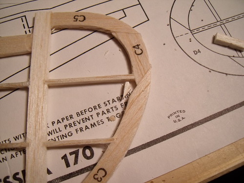
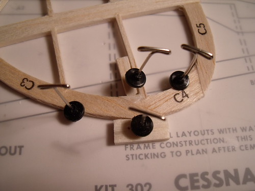
I've cut out all of the parts, and bagged them up. As per other builds the slots in the formers and ribs are too wide and deep for the stringers to be fitted, but I'll fill them if required as I build. I've got a 7" peck prop to use with this kit.
I intend to copy the kit box artwork, but use white not the very shiny Silver, which would be very difficult to do on a rubber powered model I think.
I'm going to use the kit contents other than the rubber and the Joke that is the 5" Prop that Guillows put into these series kits.
I've cut out all of the parts, and bagged them up. As per other builds the slots in the formers and ribs are too wide and deep for the stringers to be fitted, but I'll fill them if required as I build. I've got a 7" peck prop to use with this kit.
I intend to copy the kit box artwork, but use white not the very shiny Silver, which would be very difficult to do on a rubber powered model I think.
-
baedman
- Posts: 4
- Joined: Thu Sep 10, 2009 6:57 pm
- Location: Portland, OR
Plastic nose cone
Phugoid, I have completed two 300 series including the Cessena 170, and am working on a pair of 307 Piper Cherokee 140's. One of them is with kit wood and the other, my own wood. So far, with the fuselage nearly complete; kit wood 12.08 gms and my wood 8.55 gms.
I have had a consistent problem in assembling all four of these models with trying to fit the plastic nose cone over the fuselage. Perhaps I shouldn't offer advice before trying it myself, but consider sanding down the edges of the front former (B1) and dry fitting into the nose cone before building the fuselage. I envision temporarily tacking them together and a block on the backside to have something to hold onto while sanding and fitting.
I have also designed a way to convert the plastic nose cone to be removeable. PM me if intrested.
Bruce
-
Phugoid
- Posts: 952
- Joined: Wed Jan 20, 2010 8:17 am
I've decided to make the tail surfaces adjustable to ease trimming.
This means spliting the tailplane (stab). I've done this pretty well much along the line indicated on the plan for the elevator split line. Once this has dried and sanded flat, I'll radius the leading edge of the elevator and join the two parts with hinges made from the wire found in plastic bag closures.
Because this design has plenty of meat in the outline pieces, I've notched in the 1/16" x 3/32 pieces, this is considerably stronger than a simple butt joint.
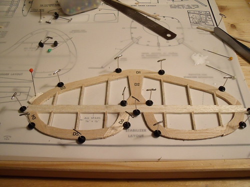
-
Phugoid
- Posts: 952
- Joined: Wed Jan 20, 2010 8:17 am
-
Phugoid
- Posts: 952
- Joined: Wed Jan 20, 2010 8:17 am
As ADW pointed out I'm going to use wire from metal bag "twisty" closures or the slightly stiffer ones they use for keeping cables neat on new electrical goods. They should be stiff enough to hold the rudder or elevator in the position I set it too whilst I trim. I will lock them in position with a drop of CA once I'm happy
As I'm buiding for rubber free flight I won't be adjusting them a lot in comparison to the constant too and fro in an RC build, therefore they won't snap. I definitey wouldn't recommend this method for RC use, fabric or flexible plastic would obviously be a better choice for that...
As I'm buiding for rubber free flight I won't be adjusting them a lot in comparison to the constant too and fro in an RC build, therefore they won't snap. I definitey wouldn't recommend this method for RC use, fabric or flexible plastic would obviously be a better choice for that...
-
Phugoid
- Posts: 952
- Joined: Wed Jan 20, 2010 8:17 am
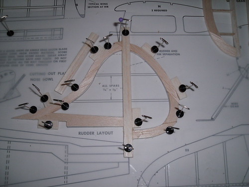
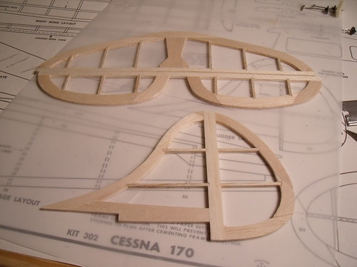
The fin is now completed. The wood that Guillows sent was much lighter but a bit "fluffy" and crushed at the die cut edges which means that in important areas a bit of patching is required. This part of the fin is an example, if I don't sort it and the tissue adheres to the "dip" then a nasty wrinkle will form, so the bad bit is cut out and a piece of scrap is cut to fit:
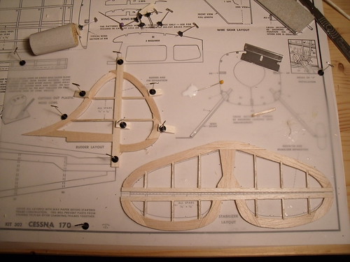
This is the glued in place with a decent bit of pressure:
All the tail feathers are done for now, I'll finally sand and seal them later
This is the glued in place with a decent bit of pressure:
All the tail feathers are done for now, I'll finally sand and seal them later
-
StefanJ
- Posts: 108
- Joined: Mon Feb 28, 2011 9:46 am
Another great thread for newbies to learn from.
I'm thinking of giving the rudder and stab of my upcoming Arrow build the hinge treatment.
What do you use to attach the twist-tie wire to the balsa? On a rocketry boost-glider I'd use glue and fabric, but I suspect that would be too heavy.
And how many pieces . . . maybe top, middle, and bottom?
I'm thinking of giving the rudder and stab of my upcoming Arrow build the hinge treatment.
What do you use to attach the twist-tie wire to the balsa? On a rocketry boost-glider I'd use glue and fabric, but I suspect that would be too heavy.
And how many pieces . . . maybe top, middle, and bottom?