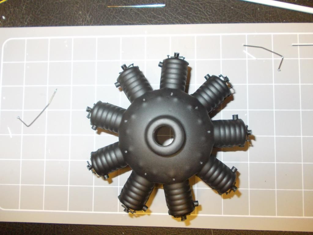
The Oberursel Factory

Ask other modelers for a little help / knowledge ?
Post Reply
Mitch
Posts: 1350
Joined: Mon Aug 22, 2011 9:16 pm
Location: Kent, WA

The Oberursel Factory

Post by Mitch »

My First Prototype...
Image
My Second Edition...
Image
What it should look like...THIS IS A PICTURE OF THE REAL ENGINE
Image
For my next generation engine... check back next week as my Fokkers will soon require engines... Mitch
Last edited by Mitch on Sun Dec 16, 2012 7:42 pm, edited 1 time in total.
twospruces
Posts: 96
Joined: Tue Nov 20, 2012 9:27 pm

Re: The Oberursel Factory

Post by twospruces »

Holy smokes! Nice detail! Given you will need nose weight, maybe you could bend copper tube and add that in ;)

Like i said, you set the bar high. Great stuff..
Mitch
Posts: 1350
Joined: Mon Aug 22, 2011 9:16 pm
Location: Kent, WA

Re: The Oberursel Factory

Post by Mitch »

The last pic is the REAL MOTOR, picture off the internet...

My engines look okay from several feet away... My NEXT generation motor WILL use copper tube from Hobby Shop, I will use 3rd photo as a guide...

AGAIN the third photo is the REAL engine... Williams Bros make engine kits, but they are of larger scale... Check back next week... today PARTY tomorrow SEATTLE M/C SHOW... Monday... HOBBY SHOP and start on the Radial Engines... I will keep you posted... Mitch

PS For my NEW generation motors, I plan MORE detail. ALL the BALANCING weight in these radial engine models is IN the motor.

UPDATE: As far as I know there were 4 manufactures of a Radial Engines during WW1... Le Rhone, Oberursel (copy of Le Rhone), Gnome, and Clerget. As far as I have seen the Le Rhone and German Oberursel look identical. I have not seen differences in the Gnome, the Clerget looks a bit different, mainly 2 rods in the front as in my D-8. All my radial engines are reinforced for rubber power and just pop out. So I can change them out if desired :D M

If anyone has anymore info on Radial Engines I would gladly take any input... Hope to build a few next week... Let's see I will need at least 5... :shock:
BillParker
Posts: 1031
Joined: Sat Jan 19, 2008 1:21 pm
Location: Houston, Texas
Contact:

Re: The Oberursel Factory

Post by BillParker »

Powerplant: 1 × Clerget 9B 9-cylinder Rotary engine, 130 hp (97 kW):

Image

Image

Image

Image

Image
William H. Parker Jr. (Bill Parker)
President, Parker Information Resources
http://www.parkerinfo.com/ap.htm bparker@parkerinfo.com
Bill Gaylord
Posts: 904
Joined: Sun Nov 09, 2008 1:29 pm
Location: Grove City PA

Re: The Oberursel Factory

Post by Bill Gaylord »

Mitch is the radial engine made from your own vacuum molds?
The curved manifold pipes are an interesting area. I see Bill has used aluminum tubing, which is not easy to bend and shape like that. I'm still working on heat bending plastic tubing, while trying to not kink or collapse it, creating smooth curves. As of now, I often have to build up and sculpt areas with thick CA, using activator for rapid curing. Making 12 accurate exhaust manifolds for a Heinkel HE51 was interesting.
squirlye
Posts: 70
Joined: Fri Jul 06, 2012 6:20 am
Location: Vail AZ.

Re: The Oberursel Factory

Post by squirlye »

Hey Bill, whats the story behind the sign on the sopwith camel ?
BillParker
Posts: 1031
Joined: Sat Jan 19, 2008 1:21 pm
Location: Houston, Texas
Contact:

Re: The Oberursel Factory

Post by BillParker »

Ha Ha! I don't really remember... Hummm... Seems like I had the thing on the table in the garage waiting for my neighbor to come take it to his house for hanging, and I found that placard sitting on my workbench... Just being a wise guy, I added the tape and put a phone number on it...
William H. Parker Jr. (Bill Parker)
President, Parker Information Resources
http://www.parkerinfo.com/ap.htm bparker@parkerinfo.com
Mitch
Posts: 1350
Joined: Mon Aug 22, 2011 9:16 pm
Location: Kent, WA

Re: The Oberursel Factory

Post by Mitch »

Hi All...

The First 2 pics are of the current engines I built. I made both these while aboard ship and no access to hobby store. Only used paper clips, T pins and paint... Things I had on hand.

The 3rd picture is off the internet of the REAL engine. I started this post to see the responce and what others have done.

I plan to go to Hobby shop to get copper or brass, and start work on my engine on Monday... I will post the NEW build as I do it... I am still unsure how much detail I can put on the Guillows Vacuform Mold. I will post my progress each day. I hope to make the Guillows Engine a closer copy of the real thing.

This is a great place to show off ones work as the engine is exposed and the first thing that the observer will see. Weight is no concern as I rather add detail then just fill up the cylinders with clay. :D Mitch

SO... What I see on the real deal is ONE pushrod that works 2 valves... My question to you all is what is the protrusion near the top of the cylinder on the left. I assume it the Spark plug? Looks like there are 2. Did these engines have Twin Spark for better ignition? I will search the web and try to find out more.

WELL... That didn't take long... found some more pics...
Image
Mitch
Posts: 1350
Joined: Mon Aug 22, 2011 9:16 pm
Location: Kent, WA

Re: The Oberursel Factory

Post by Mitch »

Before I begin... to make my job easier... I collect all tools and building materiels...
Image
I may also use 2 part epoxy and I have that on hand. And of course paint.

My plan is to replicate a typical WW1 radial engine, including:
1. Rocker cams
2. Single push rod
3. Spark Plug with ignition wire
4. Exhaust Manifolds

I should be able to fabricate something that looks good with my 3 foot rule:
My 3 FOOT RULE:
One does not need to make more detail than someone can see from 3 feet away... The typical distance the average viewer will be looking at your model.

Of course I like to use free stuff whenever I can... Paper clips, staples, coffee or soda staws, etc...
But for this project I decided to buy specific supplies for the project... I have an idea in my head and plan to start work now... I will post my progress tomorrow...

So I am starting with the basic Guillows Vacum Mold of the Dr1 Engine. It was cut out from the sheet so it still needs to be sanded. :D Mitch
Mitch
Posts: 1350
Joined: Mon Aug 22, 2011 9:16 pm
Location: Kent, WA

Re: The Oberursel Factory

Post by Mitch »

Day 1:
1: I sanded the 2 halfs flat until the flash was removed. Check for fit.
2: Added 3 supports. They are epoxied to the bottom half only... Let dry 5 minutes or so... Sand of top of supports for fit.
Image
3: Using Testors Model Master liquid cement apply glue, mate two halfs together
4: Secure with rubberbands and let dry overnight.
Image
5: Remove rubberbands and sand tops flat, and trim side of cylinders. (These Vacum forms are not as accurate as molded plastic)
6. There are some gaps and I fill will a bit more glue.
Image
At this stage, one could paint and say its done... I am just starting...
7. Check fit with cowl to see how much room I have for details...
Image
Not much room, but we'll make it work out...
TO BE CONTINUED... Mitch
Bill Gaylord
Posts: 904
Joined: Sun Nov 09, 2008 1:29 pm
Location: Grove City PA

Re: The Oberursel Factory

Post by Bill Gaylord »

Saw the plans for detail that you have. I once attempted to actually place bumps on an outrunner, to actually drive the rockers. Gave up on that idea, :D but still had pivoting rockers with all the springs. One of these days I'll have to try it, with a slightly larger setup.
Image
Mitch
Posts: 1350
Joined: Mon Aug 22, 2011 9:16 pm
Location: Kent, WA

Re: The Oberursel Factory

Post by Mitch »

Day 2:
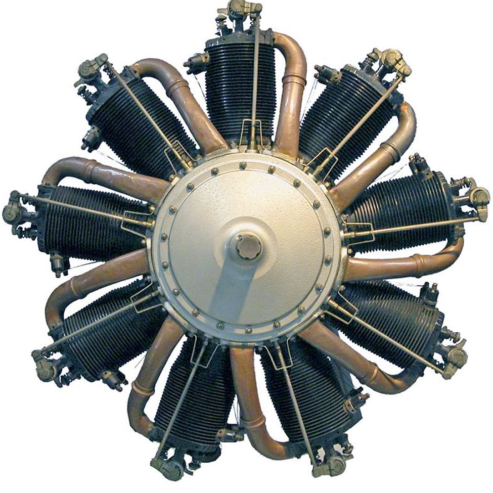
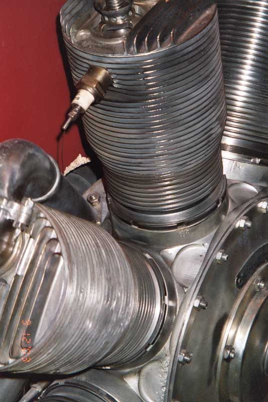
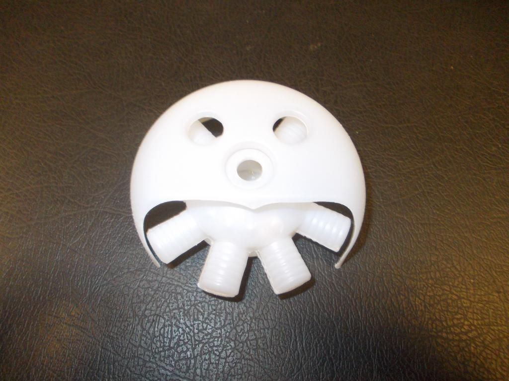
Not much done today but here is the progress... Remember, I am only trying to make the vacuform engine look better... not an exact copy...
Image
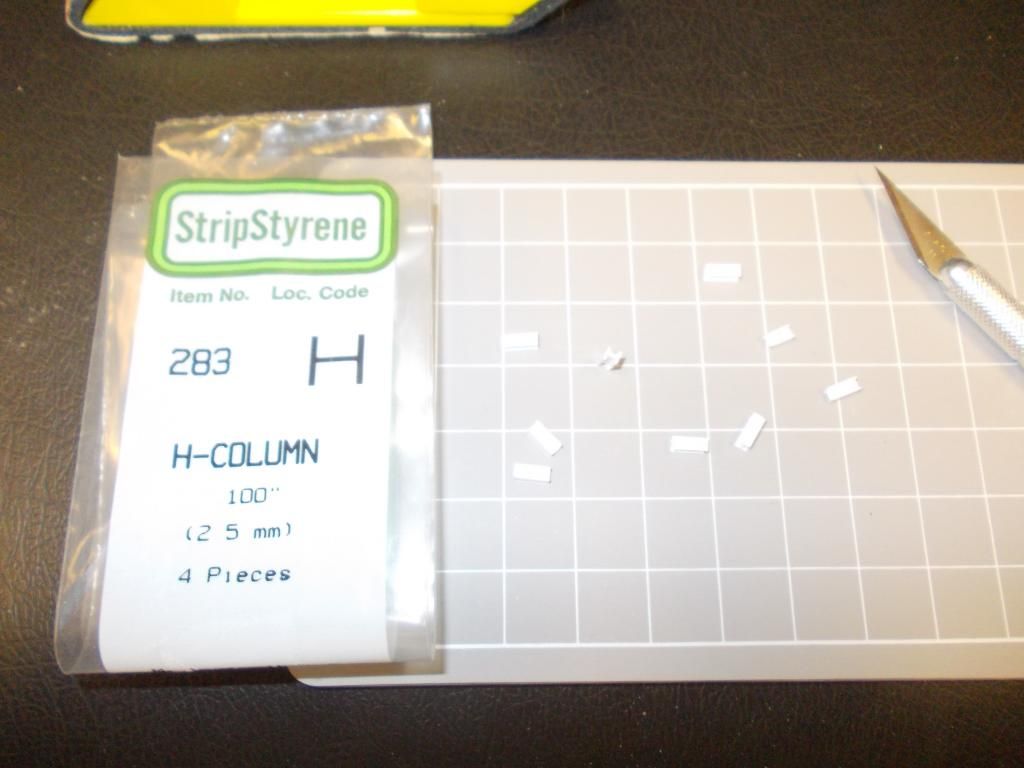
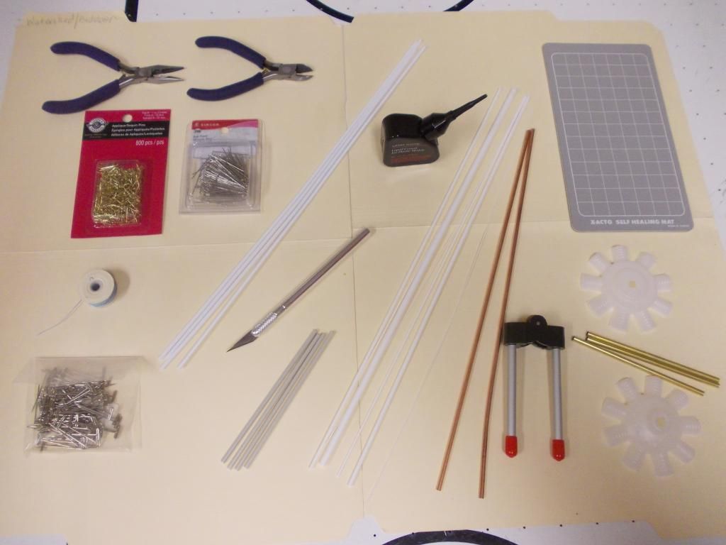
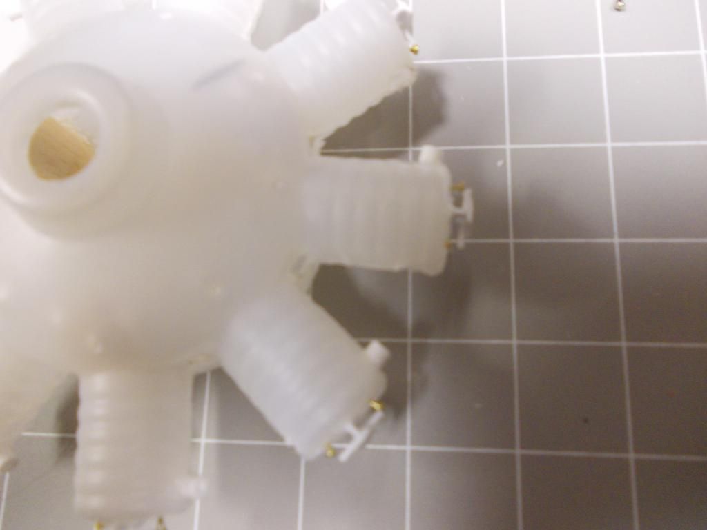
Used Strip Styrene #283 H column... cut bits about 1/4 inch
Image
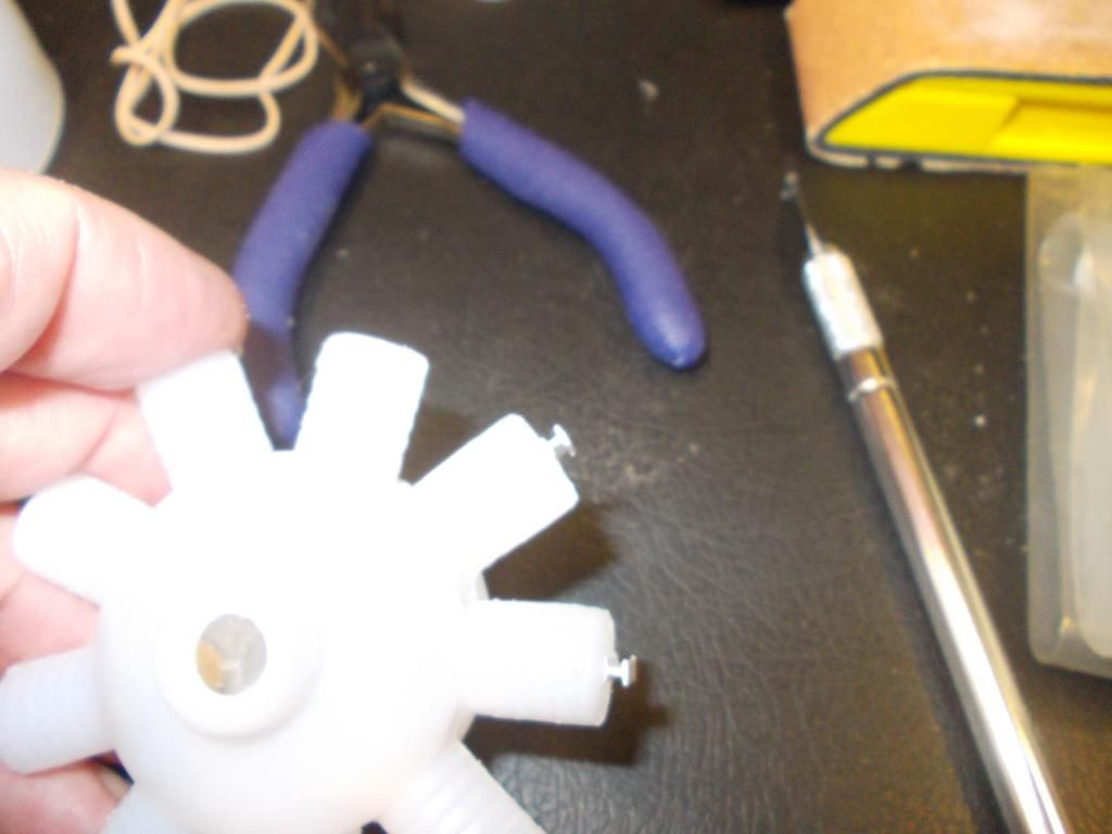
Glued these on top to make a T (The Rocker Arm)
Image
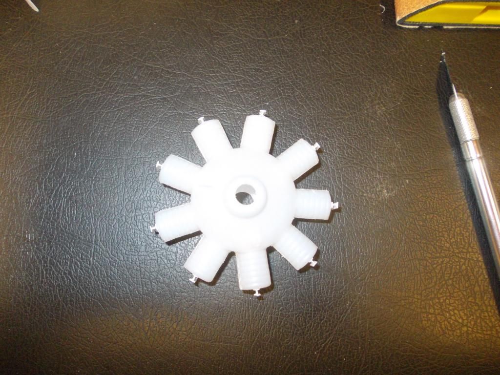
Here they are drying... so far so good...
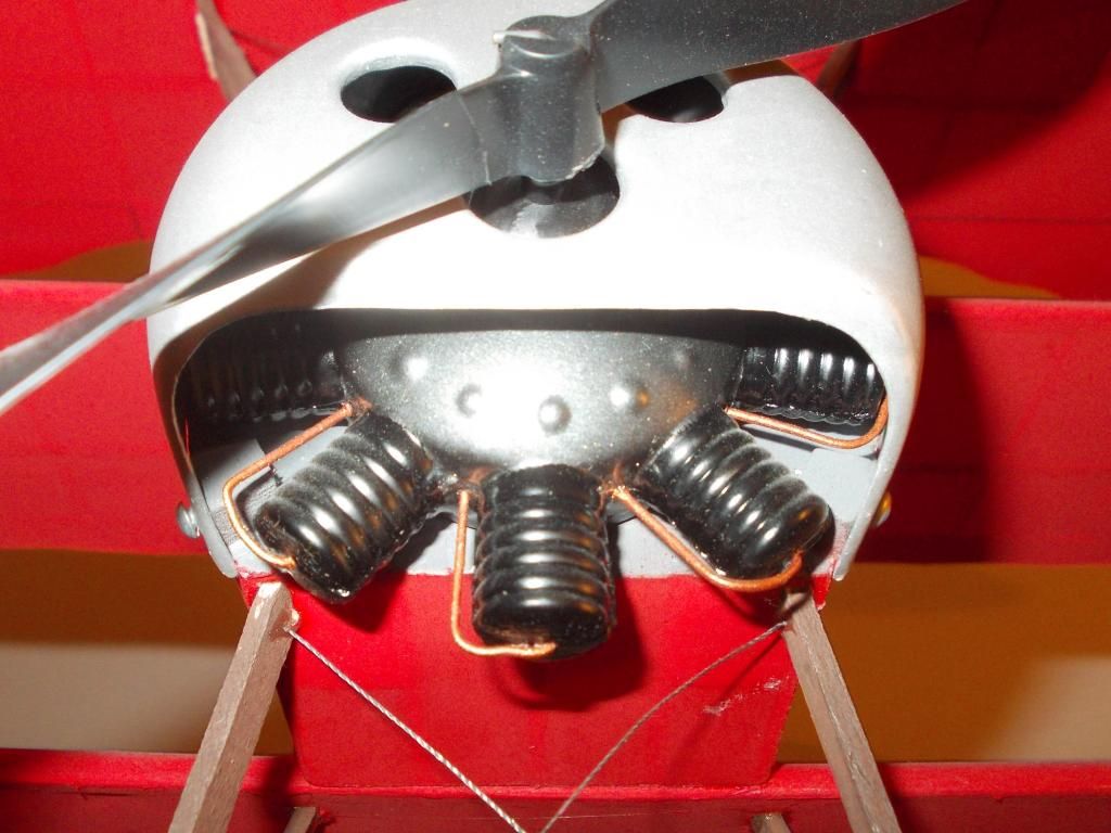
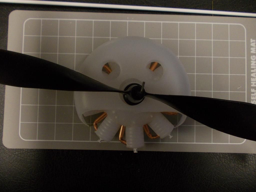
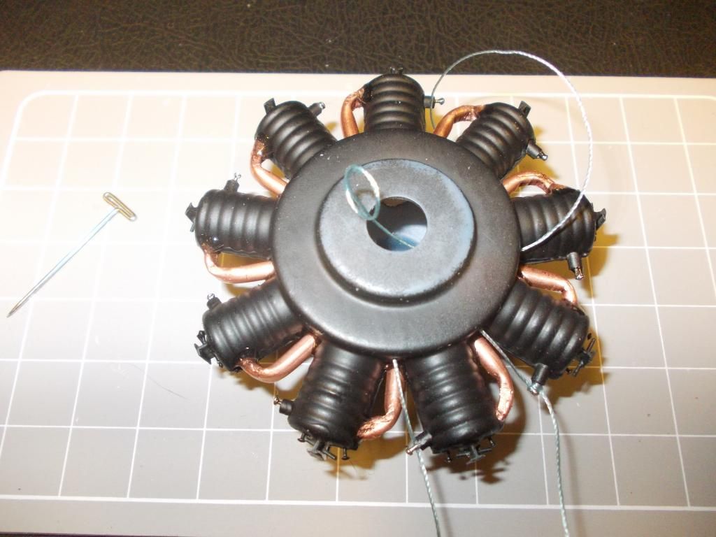
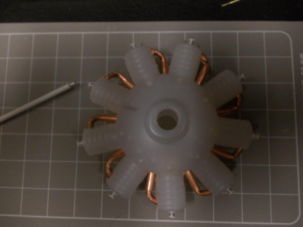
Next I found it difficult to bend the copper... Here is the work so far...
Image
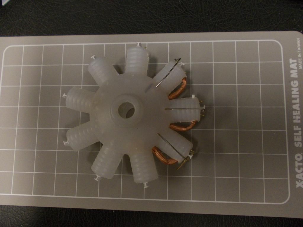
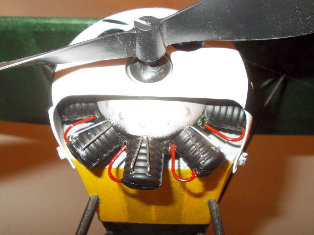
I think it will look better when painted... I plan to insest the exhaust pipe and rocker arm after paint so they will stand out...

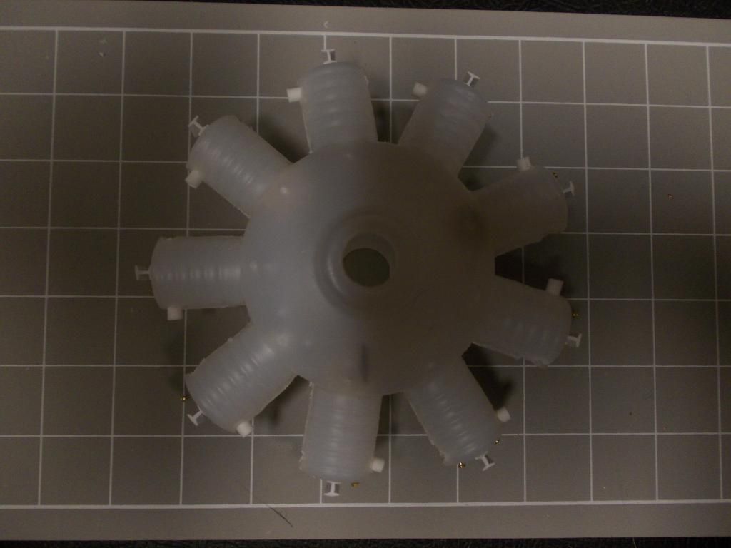
You see it as I make it... This is a work in progress...

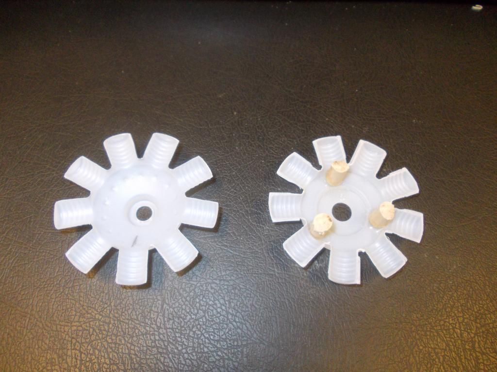
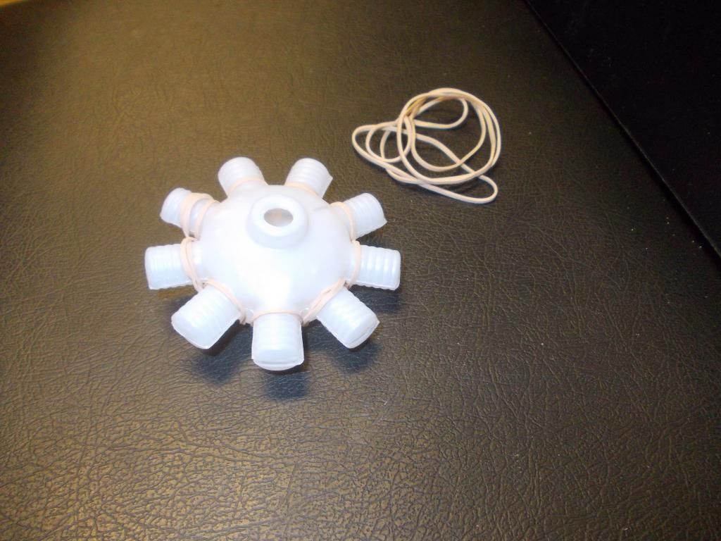
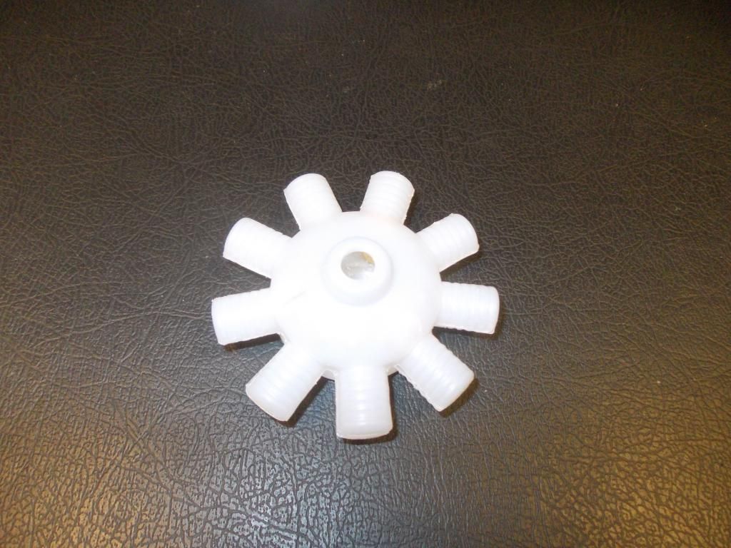
So the plan is... 2 small pins on top to simulate valves. I can pass another small pin though the "T" to simulate the rocker, this will be trimed.
The small white plastic on the left side is the spark plug and I can add thread for the ignition wire...

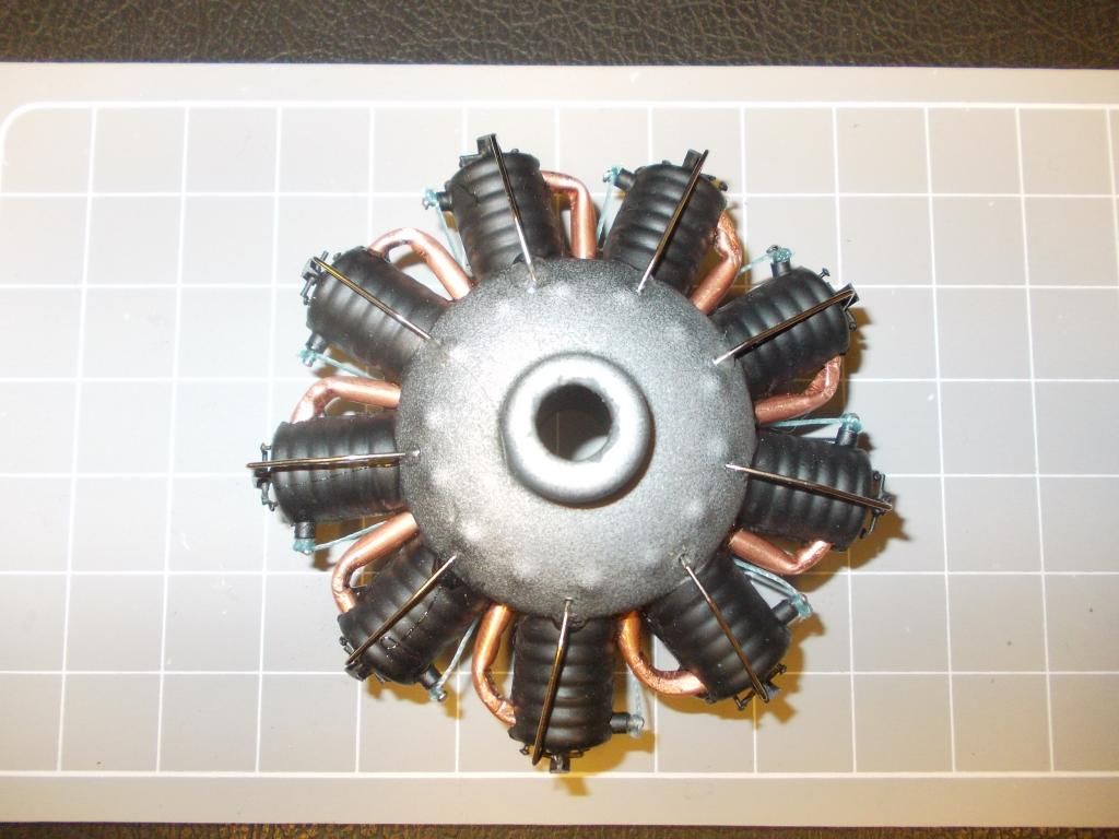
You are seeing this close up... When finished and painted and viewed from "3 FEET AWAY", I think it will be OKAY...

Questions and Comments welcome... Mitch...

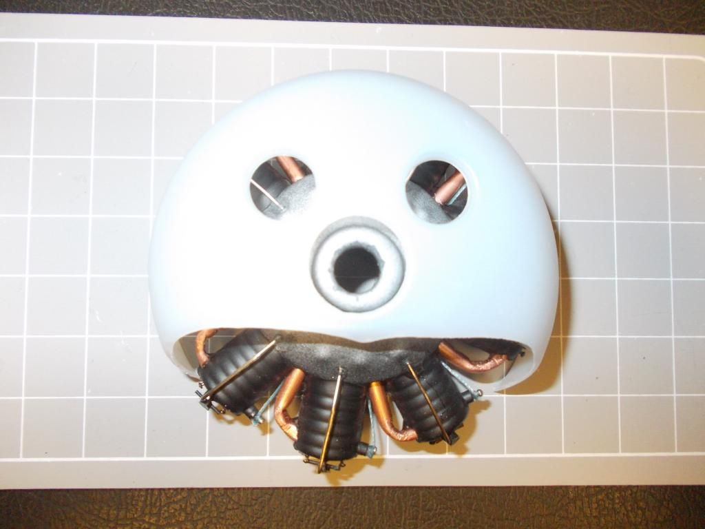
PS: This engine is planned for my D6 project... The best 3 pistons will be placed on the bottom in full view... When I perfect this process I will place better engines in other projects...

UPDATE: Finished the exhaust pipes... replaced 3... All from one piece of 1/8 in copper
Image
Also plastic on left will be socket and pin will be spark plug...thats all for tonight...
Mitch
Posts: 1350
Joined: Mon Aug 22, 2011 9:16 pm
Location: Kent, WA

Re: The Oberursel Factory

Post by Mitch »

Day 3:
Not much today... got a test fit in the cowl...
Image
Removed exhast pipes to work on plastic... Glued in Spark Plug "holders" (small plastic tube) I will slip in a pin and glue that in place (That will be the spark plug). I will be able to attach "wire leads" to the pin head. This will be done last.
Image
I'll let the project dry before I do anymore... Mitch
NOTE: Bently produced a radial engine in WW1 also... so that brings # of mfg's to 5. I know the German's used captured engines when they could. I believe the German made radials were always in short supply.
Mitch
Posts: 1350
Joined: Mon Aug 22, 2011 9:16 pm
Location: Kent, WA

Re: The Oberursel Factory

Post by Mitch »

Day 4:
Last night I finished inserting the rocker arms... made from plastic rod. Everything glued with plastic cement and left overnight to dry. So now all the plastic parts are assembled and the "valves" (small pins) are in postion and also glued in place.

I will spray with black primer, then I can paint and do final assembly.
Image
I just set the valves and rocker arms in different position at each cylinder.

After paint I will install, Exhaust Pipes, Pushrods, and Spark plug tip with wire

I will update at the end of the day... Mitch

UPDATE: Okay the motor is now primed... I will paint latter today and add details tonight...
Image
PS: It now photos better as I can use a flash, before there was too much glare.
Mitch
Posts: 1350
Joined: Mon Aug 22, 2011 9:16 pm
Location: Kent, WA

Re: The Oberursel Factory

Post by Mitch »

Day 5; Engine gets completed...ready for shipment to the Fokker Factory...
Here is a picture of the engine recieving the "Ignition Wires", pass thread through a hole. Overhand knot, wrap thread around "Spark" and another knot.
Image
After all "Wired Up' a drop of CA glue (I hate this stuff, but it has its moments), and trim the excess...
Image
Final "Fit Check" inside of cowling... a bit tight, but it will work...
Image
So, there it is, in 5 days. Maybe a total of no more than 5 hours work... I think more like 2... We have an engine that looks good...

OKAY...just recieved an order for a dozen more... got to get back to work... :shock: Mitch

PS To see this engine installed check over at the Fokker Factor when I update that! :D
Post Reply